Overview
Vertical inclinometer is the primary monitoring instrument used to measure the horizontal subsurface deformation in a borehole. It can be used to monitor the lateral deformation of soil and rock in the different geotechnical applications such as deep excavations, diaphragm and retaining walls, high open excavation and stability of embankments. In general, there are two types of inclinometers: portable inclinometers and in-place sensor systems. However, the first type is more commonly used in geotechnical projects. The portable vertical inclinometer consists of a guide casing embedded in the ground, a portable bi-axial wheeled probe, a graduated control cable, and the readout data acquisition system. The probe travels along the casing using the cable, measures the deflection of the casing and transfers the data to the readout unit.
Application
The main applications of vertical inclinometers in geotechnical monitoring are, among others:
Monitoring slope stability,
- Monitoring piles and diaphragm walls performance and deflection
- Monitoring excavations, specially near facilities and buildings
- Monitoring deformation in embankments and earth dams
- Landslide investigation
- Control and monitoring of soil retaining structures
- Ground deformation due to tunneling
- Investigation of subsurface shear zones
Installation and operation
The portable vertical inclinometer consists of a guide casing embedded in the ground, a portable bi-axial wheeled probe, a graduated control cable, and the readout data acquisition system. The probe travels along the casing using the cable, measures the deflection of the casing and transfers the data to the readout unit.The portable vertical inclinometer consists of a guide casing embedded in the ground, a portable bi-axial wheeled probe, a graduated control cable, and the readout data acquisition system. The probe travels along the casing using the cable, measures the deflection of the casing and transfers the data to the readout unit.
The inclinometer casing has two pairs of grooves in two perpendicular directions to guide the probe in a given directions. The two directions are usually referred to as Axis A and B. The casting is vertically installed in the borehole, embedded in the ground, or cast into concrete. It has usually a diameter of 58 or 70 mm and is designed to deform with the adjacent ground or structure.
For the measurements, the inclinometer portable probe is placed in the casing and readings are made from bottom to the top at intervals of 50 cm. The intervals are controlled my metallic marks on the cable passing through a notch in the cable gate. At each reading, the tilt on both axes (deformation) are measured and acquired by the data acquisition system. Once the probe reaches the top of the casting, the probe is rotated 180° and a second reading is made in the same way from bottom to top. The two readings eliminate the errors and provide a full horizontal profile of the casing. Results are often presented in terms of cumulated and incremental displacement profiles with the assumption that the bottom of the casting is fixed and free of movement.
It should be noted that the inclinometer probe is equipped with a bi-axial sensor. Therefore, when reading is made in Axis A, results are obtained not only for the primary axis A but also for the secondary axis B. However, the precision of the device in the secondary axis is usually lower; therefore, sometimes readings are made on both directions (two pairs of readings: 0-180° on Axis A and B).
The other type of vertical inclinometers is the in-place inclinometer. It consists of one or more sensors positioned on the zone of suspected deformation and connected to a data logger. This type of inclinometers is rarely used in common geotechnical practice and is mainly useful for very particular cases where a continuous monitoring is required for construction or safety purposes.


Figure 1. Inclinometer casing (left), inclinometr setting (right)
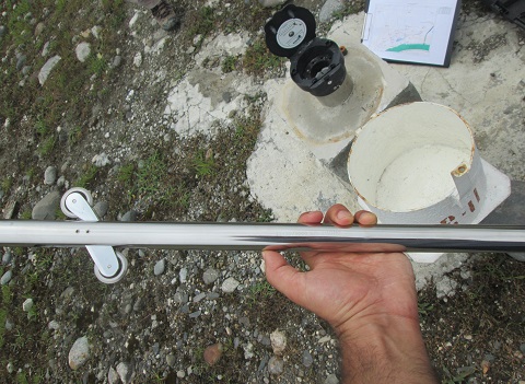
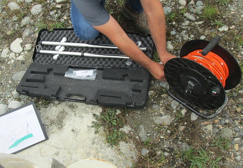
Figure 2. Inclinometer probe (left), inclinometer package including cable, proble and calibration probe (right)Inclinometer probe (left), inclinometer package including cable, proble and calibration probe (right)
Advantages and limitations
Advantages:
- An efficient way to monitor the lateral displacement and sheared zones
- The installation is relatively simple
- The system is usually roboust, stable and reliable in long term
- The system is usually designedAccurate and precise measuremen
Limitations:
- Lateral displacements are calculated based on the assumption that the bottom of the casing is fixed and has no movement. If the bottom is not fix, the measured displacements will represent relative and not absolute values. Solution: it is recommended to measure the displacements at the casing head using geodetic monitoring and compare it with the inclinometer results.
- Measurements will be discontinued in case of shearing of the casing due to large displacements.